
I started with STM32 like I start with every microcontroller by reading the datasheet. As it turned out, this is not the best way to go about this. Understanding the basics of the architecture is important but a visual representation of the clocking logic for example can save you a lot of time.
In this post, I will explore the tools and essentials to start out with STM32, and we will do a simple project where we just toggle an LED. Let’s get started!
The IoT Discovery Board
The IoT Discovery Board, also called STM32 IoT node, is a development board packed with sensors and connectivity modules. A simple use case is to configure the board to push the readings of some or all of its sensors to the cloud using a cloud vendor IoT service. From there, you can use the data as you please. The code name for the board is B-L475E-IOT1A
The board uses STM32L475 MCU which is based on ARM’s Cortex-M4 architecture. The MCU chip has hundred pins. Most chip pins is connected to the modules on-board such as the WiFi and the USB OTG modules. The reminder of the pins is connected to Arduino connector IO pins for your usage. How you can use these pins depend on your configuration and what peripheral these pins can be used for. For example, the pin group labeled CN2 is power and control pins only. A full board layout can be found on MBED website.
Development Environment
Linux is my operating system of choice. Keil uVision IDE, MDK-Arm version, is a popular choice for STM32 development, but it has no Linux support, and it doesn’t support some of the important features we will be using in this post. On the other hand, there’s STM32CubeIDE which supports Linux and is based on Eclipse® IDE.
STM32CubeIDE has some important features such as MCU pinout and clocking diagrams; if you’re not comfortable writing code for all configurations yet, STM32CubeIDE makes it easy to configure peripherals and pins using GUI tools, and the IDE will generate the necessary code for you.
Using HAL
STMicroelectronics provides what’s called Hardware Abstraction Layer, HAL. As the name suggests, HAL provides an API that’s independent of the hardware. It goes by the MCU family; in our case, we would use HAL for STM32L4. HAL will save you a lot of time by making simple API calls rather than directly manipulating registers’ values. For example, to toggle a GPIO pin such as B14 directly, you would write.
|
|
With HAL, you only need to make one API call.
|
|
The most important benefit is that you can move easily between boards without feeling the difference, and that’s what hardware abstraction means. However, it’s important to be aware of the overhead it comes with in terms of program size and possible limitations. For some applications, it won’t be a problem but others where you’re working with limited RAM, you might want to consider writing to registers directly. STM32CubeIDE uses HAL by default. The STM32L4 HAL reference document can be found here.
Using STM32CubeIDE
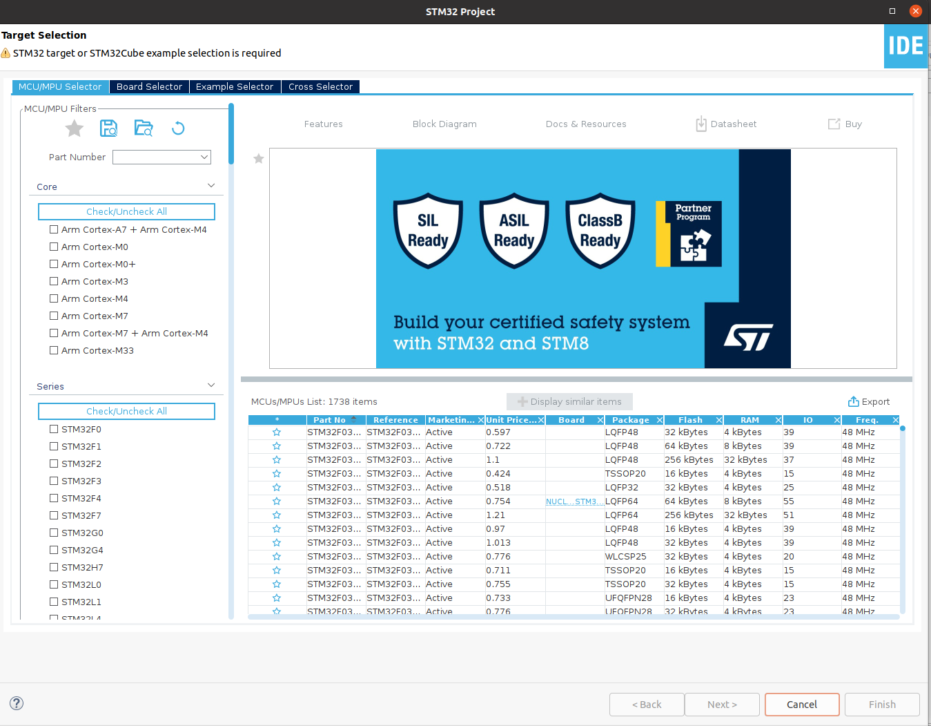
B-L475E-IOT1A2 board. Choosing the board rather than the MCU will initialize the onboard peripherals for you. The first time you create a project for a specific MCU or board, the IDE will take some time to download related files. Let’s take a look at the file structure for the project.
|
|
At the top level, we care about the ioc file and the Core directory. The Core directory is where all your C headers and files reside. STM32CubeIDE auto generates main.h and main.c for you. It’s very important to note when editing theses files, your code must go inside a USER CODE block; otherwise, it will be deleted the next time the IDE generates code for you. Following is an example of user code blocks inside main.c.
|
|
Note that everything outside the USER CODE blocks was generated by the IDE. Now, let’s move on to the ioc file. For us, it contains two important diagrams which are extremely helpful visualization tools. The first is the pinout diagram.
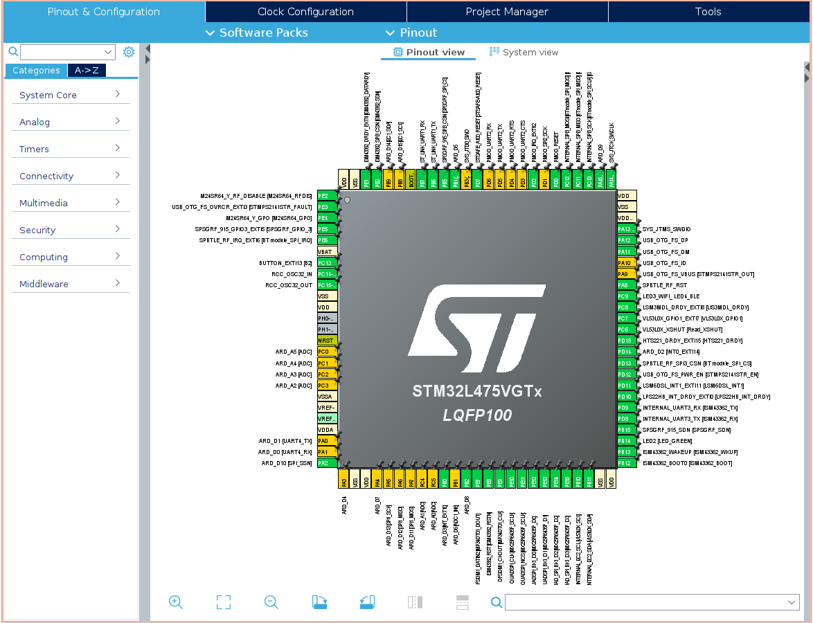
As you can see, the pinout diagram shows the MCU chip with each pin labeled. The labels takes the color green if it’s fully configured, yellow if it’s connected to a module/peripheral but not configured, and grey if the pin is at reset state.
You can click on any pin to configure it for your use. You can also see a list on the left which has all the supported peripherals for you to configure if needed. Next is the clock configuration diagram.
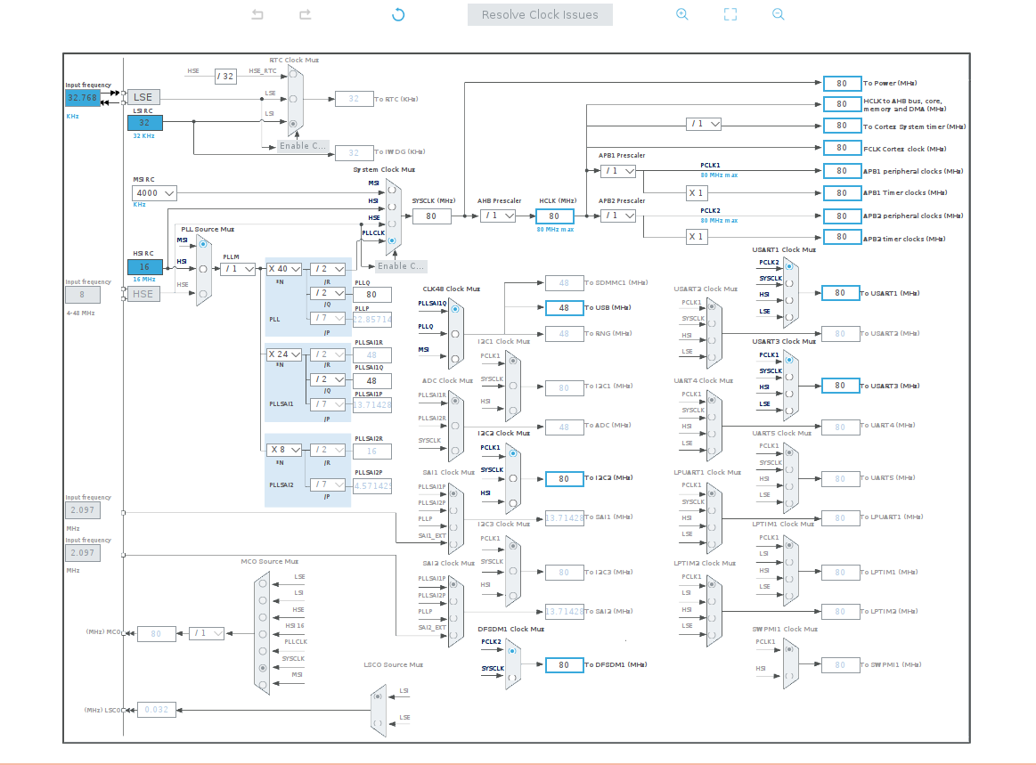
Many of STM32 MCUs come with multiple clock sources to choose from such as Multi-Speed Internal oscillator, known as MSI, and High-Speed Internal oscillator, known as HSI; that’s just two out of many options that depends on the MCU you’re using. And then we have Phase Locked Loop, PLL, which is used to scale up the frequency. In simple words, clock configuration is hard if you’re dealing with code only without a diagram to show you which is which. The clock configuration diagram from STM32CubeIDE makes the job much simpler by using multiplexers and dropdown menus, you can do the clock configuration quickly and efficiently.
After manipulating the diagrams or the configurations of the ioc file, the IDE will generate code for said changes. If that doesn’t happen for some reason, you can force the code generation by right clicking on the project and choosing “Generate Code.”
Blinking an LED
The IoT Discovery Board comes with two USB micro connectors. One of them is labeled as ST-Link; a debugging module from STMicroelectronics. We will be using the ST-Link to connect the board to PC, but before we do that, let’s make sure the power jumper is placed correctly. If you flip the board upside down, you will find a jumper labeled JP4; ensure that JP4 is set to 5V_ST_LINK.
We will use one of the LEDs onboard to demo our small project. The board has plenty of LEDs, many of them are used as status indicators for onboard modules such as the WiFi module. We will use LED2 located next to the ST-Link USB connector.
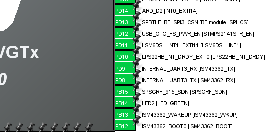
If you used the board selector when creating the project, LED2 will be configured and ready to use. From the pinout diagram, we see that the LED is connected to PB14. We just need to add the code to toggle the pin every one second. Inside the forever loop in main.c, we will add:
|
|
The function HAL_GPIO_TogglePin simply toggles the output pin from high to low and vice versa. It accepts two arguments; the first argument is the GPIO line, in our case it’s B, and the second argument is the pin number which is 14. The HAL_Delay function creates a delay of x milliseconds with x being the argument you pass. Simply click run when you’re ready.
Resources for the IoT Discovery Board
Here’s a list of resources for your convenience, some of which was mentioned already.
| Resource | Link |
|---|---|
| STM32L4x5 Info Page | https://www.st.com/en/microcontrollers-microprocessors/stm32l4x5.html |
| STM32L47xxx Reference Manual | https://www.st.com/resource/en/reference_manual/dm00083560-stm32L47xxx-stm32l48xxx-stm32l49xxx-and-stm32l4axxx-advanced-armbased-32bit-mcus-stmicroelectronics.pdf |
| HAL for STM32L4 | https://www.st.com/resource/en/user_manual/dm00173145-description-of-stm32l4l4-hal-and-lowlayer-drivers-stmicroelectronics.pdf |
| IoT Discovery Board Pinout | https://os.mbed.com/platforms/ST-Discovery-L475E-IOT01A/#board-pinout |
Thank you for reading, please let me know if you have any questions or comments.